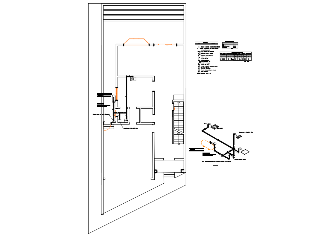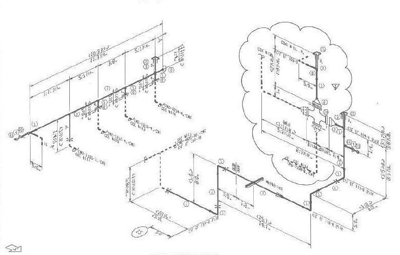
 Piping Isometrics Brief on GA drawing/Piping Plan drawing/ Piping Layout drawing. Plant and Instrumentation diagram (P&ID). General Arrangement Drawing (GAD) or Piping Plan drawing. The types of piping drawing required are as follows: A single drawing is never enough for defining the nature, scope, and layout of a project construction site. To Know more about Piping Isometric, please follow our this Article Specially written about Isometricsįor planning and constructing a project, we need to refer to multiple drawings to extract all data required. Information we gain from the Plot plan layout. Brief on Piping and Instrumentation Drawing (P&ID). Information we gain from the Process flow diagram. Checklist for General arrangement drawings.
Limitations of General arrangement drawing/ Piping Plan drawing.Information we gain from Piping General arrangement drawing/Piping Plan drawing.Some terminology frequently used in Piping GAD are:.
 Brief on GA drawing/Piping Plan drawing/Piping Layout drawing. More to Read: What Is RF Pad? How To Calculate Reinforcement pad dimensions? Is there any limitation of every drawing? If yes, what are these limitations?. What checkpoint we must look for in every drawing?. What information do we get from each of these drawings?. What are these types of drawings drawing?. Piping and Instrumentation Drawing (P&ID)Īt the end of this article, you will be able to understand and learn the following information about all drawing types frequently used in piping. General Arrangement Drawing (GAD)/Piping plan drawing.
In this article, we will explore all those piping drawings that are required to execute piping work. Drawings describing Basic design basis and.These drawings give information with help of: In process or power piping mostly 05 types of drawings are developed which help the execution person to understand the concept developed by the designer. To resolve this problem designers developed many other drawings that can collaboratively give the required information to the end-user of drawings. Sometimes it is not possible to convey all the information through a single drawing. After designing a complete 3D model on software like SP3D, PDMS, Autodesk, etc it is important to communicate the same information to the fabrication and construction team with enough clarity.


 0 kommentar(er)
